Does anybody have the mounting diagram for lee Jrs. I have a simple sketch, and photos which I got directly from grady. However none of there measurements are from a straight edge or a corner, thus making it difficult to properly locate where to mount the bases. If anyone has done this themselves, where did you measure from? Are there any pre made templates floating around?

You are using an out of date browser. It may not display this or other websites correctly.
You should upgrade or use an alternative browser.
You should upgrade or use an alternative browser.
265 express outrigger question
- Thread starter drbatts
- Start date
fishingFINattic
Well-Known Member
Not sure were in CT you are, but my boat is in Groton - you are welcome to jump on and measure as needed.
Tim
Tim
tim, thanks for the offer I may have to take you up on it, if grady doesn't get back to me, with something a little more precise. I just really don't want to have to eyeball it. Im in norwalk.
damian
damian
Salinity Now
Well-Known Member
- Joined
- Sep 17, 2010
- Messages
- 161
- Reaction score
- 0
- Points
- 0
Please do follow up with us on this, Im looking to do the exact same thing to my 2001 in a few weeks, still searching for wishbone Le Jr's right now, but I havent even started with looking at the install process.
Any chance those sketches you have are electronic and you can email them?
Hope they follow up, are the outrigger mounting areas reinforced with plates under the glass or is it just an OEM general placement area?
Any chance those sketches you have are electronic and you can email them?
Hope they follow up, are the outrigger mounting areas reinforced with plates under the glass or is it just an OEM general placement area?
Bill_N
Well-Known Member
I may be able to help you guys out. My boat is still on the trailer at my house getting prepped for launch. I'll take some measurements and pics and post this w/e...
Bill_N
Well-Known Member
Took the pics yesterday but broke a bolt off putting the last thermostat in which took awhile to remove. Will take the measurements tonight
Gary M
Well-Known Member
drbatts said:Does anybody have the mounting diagram for lee Jrs.
If yours are gunnel mounts, I may be able to help you. I mounted my Lee's a few years ago and "learned" a few things........

Bill_N
Well-Known Member
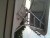
Damian, What does your sketch include? Is it a template and you just need a starting point? Here's a couple shots of my mounts. The problem as you mentioned is a good ref point. The non-skid wakway surf is good and flat so I can give you some height measurements from that. The tougher one is where to measure from fore and aft. I was thinking that the center of the molded in base for the bow rail mount would have less variation than the back corner of the windshield or hardtop mount. If I give you a dimension to the lower mount screw in each pad and a measurement for the pole supports that go on the hardtop does that do it? The pole support measurement would have to come off a hardtop mount.

Starboard

Port
Starboard
Port
Bill, thanks for the picture. Height from the walkway surface is the exact measurement I need. The measurements from grady are all from the curved surface and are horizontal measurements. I have no vertical measurements. Also where is the support bracket placed on the hardtop, relative to the curved edge and or the hardtop legs. knowing where that support bracket should be, should also help line everything up.
Bill_N
Well-Known Member
Bill_N
Well-Known Member
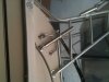
Dimensions are from the walkway surf to the center of the bottom hole in each mount pad. 2 1/8", 5", 8 3/8". Also the center of the bottom hole of the center pad is 1/4" aft of the center of the bow rail mount.
The aft pole support hole is 5/8" in front of the stud through the hardtop frame shown in this pic.

Now I can start the washing, waxing and bottom painting :mrgreen:
The aft pole support hole is 5/8" in front of the stud through the hardtop frame shown in this pic.
Now I can start the washing, waxing and bottom painting :mrgreen:
Bill_N
Well-Known Member
I'll have to look tonight. The pics aren't taken square to anything in particular so the perspective may be off a bit.
The height measurents are perpendicular to the walkway.
The height measurents are perpendicular to the walkway.
Bill_N
Well-Known Member
Measuring along the centerline of the horizontal tube from the intersection of the front hardtop support to the centerline of the outrigger tube is 13 3/4"
Got home late last night ...
Got home late last night ...
Salinity Now
Well-Known Member
- Joined
- Sep 17, 2010
- Messages
- 161
- Reaction score
- 0
- Points
- 0
Guys, Im working on mine tomorrow, the one thing I dont have any idea about is the mounting hardward, I bought mine used, and were previously mounted with through bolts, but I dont see how they would be able to through mount on the 265, the fiberglass there is WAY to thick.
Are they just using long stainless screws?
Are they just using long stainless screws?
Bill_N
Well-Known Member
Damian will have to chime in on this as he just did his. I would think they're thru bolted to backing plates to distribute the load.
the bases are through bolted to what the cust. rep at grady referred to as "the house". The instructions I got from grady was to through bolt them with large washers on the inside. This is the way they mounted them at the factory. I would have thought they would have used a backing plate but I guess not. Give me a week or so and I will let you know how my install goes.
damian
damian
Salinity Now
Well-Known Member
- Joined
- Sep 17, 2010
- Messages
- 161
- Reaction score
- 0
- Points
- 0
Well, it was definently a rookie mistake, should of taken the time to feel out the boat more......Called Grady, they told me about the access holes behind the back cushions on the port and starboard benches.
Had Wednesday off from my training schedule, so I used that time to get them on, pulled the bolsters off, found 3 access holes (factory used to mount the hardtop) and yes they are all only 1" fender washers even on the hardtop from factory.
I did my best to used thier sketch (emailed from Grady that morning) with the measurements + the #s Bill posted on the forum to find a food symetrical fit.
After alot of pencil marks and holding in place at various angles, I settled on a spot and went for it, got both sides mounted in about 4hrs. Im afraid I mounted them with too much of an aft-leading angle though, Lee's says 30degrees, but after comparing the pics of other installs vs mine, it appears mine are at a steaper angle.
Mounts I bought used, poles were new.....after all that work I was really looking forward to mounting poles and have it ready for action, opened up the box and sure enough the shipped the wrong ones (1-1/2' vs 1-3/4" as a I ordered)....so now Im in waiting for new poles and I have to go to the trouble to ship back to dealer (reembursed, but stll PIA)
Hope it all works out, it was tuff and scary guessing, but I think it will work out nicely......still TBD.
Attachments
-
 outrigger port.jpg40.4 KB · Views: 581
 -
 outrigger stbd.jpg41 KB · Views: 581