Nice - I like the use of the "CAD" technology...
")
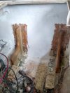
Couple quick thoughts - knee walls are nice - but from the pics, the glass looks lightweight. You'll want AT LEAST 1 layer of 1708 there.
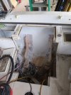
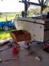
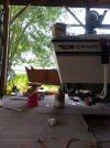
Here's some info you'll probably find info - these are pics of my boat during restoration. The changeover from I/O to OB was done before I got the boat, but the hole in the cockpit floor for the I/O was never addressed by the previous owner. I had found some soft spots so I ripped out the entire floor and rebuilt, fixing the I/O "hole", as well. It ain't super pretty, but my goal was structural soundness, not necessarily cosmetic.

postimg.cc
Just realized there's a good pic of the bracket, too.