- Joined
- Nov 14, 2023
- Messages
- 8
- Reaction score
- 4
- Points
- 3
- Location
- NE Massachusetts
- Model
- Express 330
2007 330 Express Original Factory TV and Antenna Replacement
TV REPLACEMENT:
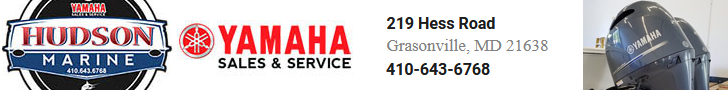
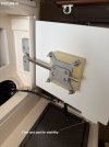
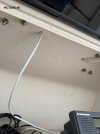
I removed the old analog “4:3” TV that came with the boat and installed a new smart TV, a 22” Insignia model. For mounting, I bolted the existing TV pivot arm to a 14”x11.75”x3/4" piece of Starboard (HDPE material), with a 4.5”x4.5”x1-5/8” (UHMW) spacer block in between. The new TV was mounted to the Starboard material using a standard 75mmx75mm TV mounting plate that I picked up at my local Best Buy.
The TV will swing out just like the old analog TV did so you can watch it while in the V-Berth. When it is moved back to the storage position, the original latch grabs the new Starboard material to lock the TV into place. I added a small plastic foot and rubber pad (1” total) to the bottom of the starboard to eliminate sagging and for stability in rough seas. It has stayed secured in place so far – no problem when we hit 3’-4’ seas on a trip last August.
(See pics 1,2 and 3)
NEW (amplified) TV ANTENNA:
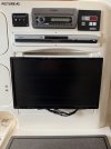
Connecting the original factory antenna to the new TV got me about 20 digital channels (most were junk – no major stations) so I wanted to install an amplified antenna to get more broadcast signal. I was hoping to use the existing antenna cable instead of running a new wire but apparently, GW placed the original antenna and wire between the outer hull and cabin structure when the boat was put together so there was no way I could get to it without sawing through my galley cabinets.
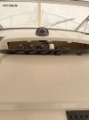
The new antenna (Shakespeare Seawatch 3004), was installed on the hard top, close to the equipment (VHF) box. I drilled through the hard top and ran the new antenna wire into the equipment box.
(See pics 4 and 5)
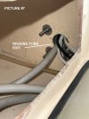
Next, I removed the helm RPM display panel to give me access to the bottom of the rigging tube.
(See pics 6 and 7)
Tip: Temporarily unbolt the bottom of the rigging tube – it makes it easier to snake the wire through the tube and into the engine gauge area.
To gain access to the lower section of the helm wiring area, the breaker panel mounting screws were removed and the panel draped forward. You can get zapped if you’re not careful here so make sure the boat is unplugged from shore power and not just turned off at the breaker panel. (The plastic guard covering the breakers was temporarily removed during the wire routing.)
(See pics 8 and 9)
Run the antenna wire down the rigging pipe and down into the breaker panel enclosure. Getting the wire through a rigging tube that already has wires in it took a bit of time but once it’s through, it’s easily passed down to the breaker panel enclosure area.
Next, drill a 5/16” hole through the very bottom of the breaker panel enclosure. Don’t drill too far or you’ll drill through the aft cabin ceiling trim. Pass the antenna wire through that hole.
(See pic 10)
To snake the wire from under the breaker panel area over to the port side of the boat, you’ll need to remove a few screws from the left end of the plastic trim piece above the aft cabin entrance.
You’ll also need to remove the aft cabin’s port side forward trim panel. This is the panel that gets you access to the underside of the cabin entry stairs and access to the CO detector wiring. There are about 6 or 8 screws and it comes out and goes back in easily. This makes snaking the wires a lot easier.
Running the wire from the breaker panel area over to the port side was the most time-consuming part of the project. It’s not easy but it is doable. There was some sort of partition or blockage so I actually had to drill a small hole into the aft cabin to allow me to route the wire into the open area near the port side equipment (air conditioning compressor area). Because I routed the wire into the cabin area, I had to cut a small notch (3/4” wide x 1.5” high) in the top-right corner of the trim panel. Most of that is hidden when the trim panel is screwed back in place.
(See pics 11,12 and 13)
Now for more fun. Remove the fridge and place it on the cabin floor on a piece of cardboard or on a thick pad. Don’t scratch that nice cabin sole! You probably won’t need to disconnect any fridge wires – mine had plenty of slack. Note that I did try to run the snake along the port side without first removing the fridge. There are blockages that prevent the snake going through and I wasted about an hour and a half before removing the fridge. After that it was very easy to route the wire along the outer wall to the area behind the new TV.
(See pic 14)
Once the fridge is out, the 12VDC-to-120VAC inverter and wires will be exposed. You can tap into the 12V feed there for the antenna amp or you can just use the 110VAC power adapter that comes with the antenna. That works out well so that when you shut off the TV breaker on the panel, the powered antenna gets shut off too.
For my installation, I connected a short 3-to-1 extension cord into the empty 110VAC socket on the inverter. (The new TV was plugged into the first inverter socket.) The extension cord runs up into the TV box area and powers the new antenna power, my Amazon Firestick and the adapter for a Bluetooth receiver for my stereo, since my 2007 vintage GW stereo doesn’t support Bluetooth.
(See pic 15)
My 330 Express had an A/B antenna/cable switch which I use so I can switch back and forth from dockside cable TV and the new antenna if necessary. The new antenna and TV setup now pulls in about 50 channels.
Good luck!
TV REPLACEMENT:
I removed the old analog “4:3” TV that came with the boat and installed a new smart TV, a 22” Insignia model. For mounting, I bolted the existing TV pivot arm to a 14”x11.75”x3/4" piece of Starboard (HDPE material), with a 4.5”x4.5”x1-5/8” (UHMW) spacer block in between. The new TV was mounted to the Starboard material using a standard 75mmx75mm TV mounting plate that I picked up at my local Best Buy.
The TV will swing out just like the old analog TV did so you can watch it while in the V-Berth. When it is moved back to the storage position, the original latch grabs the new Starboard material to lock the TV into place. I added a small plastic foot and rubber pad (1” total) to the bottom of the starboard to eliminate sagging and for stability in rough seas. It has stayed secured in place so far – no problem when we hit 3’-4’ seas on a trip last August.
(See pics 1,2 and 3)
NEW (amplified) TV ANTENNA:
Connecting the original factory antenna to the new TV got me about 20 digital channels (most were junk – no major stations) so I wanted to install an amplified antenna to get more broadcast signal. I was hoping to use the existing antenna cable instead of running a new wire but apparently, GW placed the original antenna and wire between the outer hull and cabin structure when the boat was put together so there was no way I could get to it without sawing through my galley cabinets.
The new antenna (Shakespeare Seawatch 3004), was installed on the hard top, close to the equipment (VHF) box. I drilled through the hard top and ran the new antenna wire into the equipment box.
(See pics 4 and 5)
Next, I removed the helm RPM display panel to give me access to the bottom of the rigging tube.
(See pics 6 and 7)
Tip: Temporarily unbolt the bottom of the rigging tube – it makes it easier to snake the wire through the tube and into the engine gauge area.
To gain access to the lower section of the helm wiring area, the breaker panel mounting screws were removed and the panel draped forward. You can get zapped if you’re not careful here so make sure the boat is unplugged from shore power and not just turned off at the breaker panel. (The plastic guard covering the breakers was temporarily removed during the wire routing.)
(See pics 8 and 9)
Run the antenna wire down the rigging pipe and down into the breaker panel enclosure. Getting the wire through a rigging tube that already has wires in it took a bit of time but once it’s through, it’s easily passed down to the breaker panel enclosure area.
Next, drill a 5/16” hole through the very bottom of the breaker panel enclosure. Don’t drill too far or you’ll drill through the aft cabin ceiling trim. Pass the antenna wire through that hole.
(See pic 10)
To snake the wire from under the breaker panel area over to the port side of the boat, you’ll need to remove a few screws from the left end of the plastic trim piece above the aft cabin entrance.
You’ll also need to remove the aft cabin’s port side forward trim panel. This is the panel that gets you access to the underside of the cabin entry stairs and access to the CO detector wiring. There are about 6 or 8 screws and it comes out and goes back in easily. This makes snaking the wires a lot easier.
Running the wire from the breaker panel area over to the port side was the most time-consuming part of the project. It’s not easy but it is doable. There was some sort of partition or blockage so I actually had to drill a small hole into the aft cabin to allow me to route the wire into the open area near the port side equipment (air conditioning compressor area). Because I routed the wire into the cabin area, I had to cut a small notch (3/4” wide x 1.5” high) in the top-right corner of the trim panel. Most of that is hidden when the trim panel is screwed back in place.
(See pics 11,12 and 13)
Now for more fun. Remove the fridge and place it on the cabin floor on a piece of cardboard or on a thick pad. Don’t scratch that nice cabin sole! You probably won’t need to disconnect any fridge wires – mine had plenty of slack. Note that I did try to run the snake along the port side without first removing the fridge. There are blockages that prevent the snake going through and I wasted about an hour and a half before removing the fridge. After that it was very easy to route the wire along the outer wall to the area behind the new TV.
(See pic 14)
Once the fridge is out, the 12VDC-to-120VAC inverter and wires will be exposed. You can tap into the 12V feed there for the antenna amp or you can just use the 110VAC power adapter that comes with the antenna. That works out well so that when you shut off the TV breaker on the panel, the powered antenna gets shut off too.
For my installation, I connected a short 3-to-1 extension cord into the empty 110VAC socket on the inverter. (The new TV was plugged into the first inverter socket.) The extension cord runs up into the TV box area and powers the new antenna power, my Amazon Firestick and the adapter for a Bluetooth receiver for my stereo, since my 2007 vintage GW stereo doesn’t support Bluetooth.
(See pic 15)
My 330 Express had an A/B antenna/cable switch which I use so I can switch back and forth from dockside cable TV and the new antenna if necessary. The new antenna and TV setup now pulls in about 50 channels.
Good luck!
Attachments
-
 TV mount 1.jpg225.9 KB · Views: 35
 -
 TV Front View 2.jpg305.4 KB · Views: 34
 -
 TV latched 3.jpg209.2 KB · Views: 33
 -
 Antenna Hardtop 4.jpg207 KB · Views: 39
 -
 Antenna Wire 5.jpg311.4 KB · Views: 34
 -
 Engine Gauge Area 6.jpg259.2 KB · Views: 33
 -
 Rigging Tube 7.jpg246.1 KB · Views: 33
 -
PICS_8-10.zip981.5 KB · Views: 6
-
PICS_11-13.zip1.6 MB · Views: 2
-
PICS_14-15.zip775.1 KB · Views: 2