
- Joined
- Nov 14, 2023
- Messages
- 8
- Reaction score
- 4
- Points
- 3
- Location
- NE Massachusetts
- Model
- Express 330
Parts:
Fuel Sender: KUS 33-240 ohm model KUS-SSL20 (fisheriessupply.com) with cork gasket or optional nitrile gasket, model KUS JSR00181.
Wire: 50 feet of red-yellow-black 16awg jacketed wire (Amazon #B0CX1DBFDP). I really wanted just yellow and black 16AWG conductors but I was unable to find that combo alone.
Fuel Gauge: KUS black face/bezel model KUS-CPFR-BB-240-33 (fisheriessupply.com)
Terminal strip: International Connector model 0113-10-3640-05 (Amazon #B08BDS8L3N)
Wire crimp connectors - Forks and Loops (blue)
Solder and shrink wrap
Fiberglass snake (Amazon item # B07PTSY26L)
Lenox Tools 2-1/8” bi-metal hole saw (Amazon # B004YK5D68)
The prep:
In the aft cabin, remove the square trough cover on the upper left. Once that is out, you can remove the entire starboard side wall panel (not just the small access panel). This exposes the holding tank and rigging tube area
Open the aft generator access panel and remove.
Clean the area around the existing diesel tank sender with a stiff bristle brush. Vacuum up any debris.
In the cabin, remove the breaker panel screws and carefully let it droop forward.
In the helm area, remove the gauge panel screws and the cockpit switch panel screws.
Run the sender wire up to the helm area.
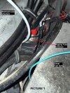
Locate the opening of the aft rigging tube, next to the starboard side of the diesel tank. The rigging tube is up fairly high and is easily accessible and this is where we’ll insert the electrical snake.
(See picture 1)
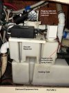
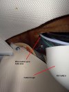
Insert the snake and work it through to the far end of the rigging tube. It will appear behind the holding tank on the starboard side of the aft cabin.
(See picture 2)
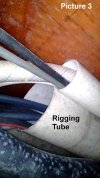
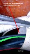
There are two rigging tubes which terminate behind the holding tank. The snake will exit from the larger of the two rigging tubes. Once the snake is visible, attach the red/yellow/black wire to the end of the snake. Tape it good with vinyl electrical tape so it doesn’t easily come apart.
(See pictures 3 and 4)
Pull the wire back through the rigging tube towards the tank area. (This is best done with a helper.) Leave about four feet of wire so we’ll have plenty of slack to connect to the tank sender. Note that with a helper, snaking the rigging tube and pulling the wire back through was fairly easy and took us less than 10 minutes total. Also note that the remaining part of this project went quicker after sending my helper home .
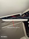
Route the wire over the waste vacuum pump and into the upper-left trough.
(See picture 5)
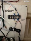
Fish the wire up from the trough into the electrical panel area (again, fairly easy). I mounted a small marine-rated terminal strip on the back wall of the panel area. It will make the necessary connections a lot cleaner and easier to troubleshoot if needed later.
(See picture 6)
Note that for the wire from that runs from the fuel tank sender to the terminal strip, the Red conductor is not used and can be cut back on both ends and covered with a piece of shrink wrap. For this tank area-to-helm wire run alone, we used a little less than 25 feet of wire.
Make the electrical connections.
Strip the yellow and black wires, add fork terminals to them and connect them to the bottom of terminal strip.
Run a (separate) black ground wire from a good DC ground buss to the black wire already on the bottom of the terminal strip.
Run a separate piece of the red/yellow/black wire, from the top of the terminal strip area up to the cockpit switch panel area, Again, we will not be using the red wire and it can be cut back on both ends. Leave plenty of slack to be able to reach the back of the gauge area.
In the electrical panel area, connect the BLACK wire to the other two black wires already on the terminal block. Connect the YELLOW wire to the yellow wire already on the terminal block.
(See picture 7)
Mount The Gauge.
Pick a spot in the gauge panel for the new gauge with plenty of space behind. I placed a rag under and behind the gauge panel to catch the cuttings.
Replace the gauge panel and screw it tight so it can be drilled in place. Drill a pilot hole at the center of where the new gauge will be mounted. Start with a small bit (I used a 1/8” bit) as it is less likely to move off your “center” mark than a larger bit would. I then enlarged the hole with a 1/4” bit.
Just a tip here: Do not rely on the hole saw’s pilot bit for your first hole as you might ruin the gauge panel if the hole saw “skates” AND IT WILL no matter how steady you think you are!!
Next, using your 2-1/8” bi-metal hole saw, start drilling the front of the panel in REVERSE (COUNTER-CLOCKWISE) rotation. This will lessen the damage to the vinyl trim covering. Once the vinyl trim covering has been cleanly cut, you can start cutting into the metal using the normal (forward/clockwise) hole saw rotation.
To lessen the chance of gouging the vinyl, drill approximately halfway into the metal and then flip the gauge panel forward so you can can finish the drilling from the back side. If you choose to drill through the entire thickness from the front, you risk having the hole saw jump when it finally cuts through. To prevent damage to the helm area while drilling, I used a wooden 4X4 under the panel (covered with blue masking tape) to finish the cut from the back side.
Insert the new fuel gauge and fasten it to the panel using the screw-on retainer. There is a rubber gasket embedded into the gauge so you shouldn’t need any silicone to seal against the weather.
Connect The Gauge Wires.
The gauge wires attach to the gauge with a removeable connector. If already plugged into the gauge, disconnect the connector so we can solder the connections easier.
Strip the yellow and black wires (about 3/8”) coming from the terminal strip up to the switch panel area. As before, cut the red wire back and cover it with a small piece of shrink tubing. Since we have two new wires now coming from the switch panel (the red power wire and the blue lighting wire), tie them together with the black/yellow/red sender wire so we can snake a single wire group to the gauge.
Place a small piece of shrink tubing over the black wire and solder it to the gauge connector’s BLUE wire (DC ground).
Place shrink tubing over the yellow wire and solder it to the gauge connector’s BLACK wire (fuel sender signal).
Solder a (separate) piece of red wire to the gauge’s RED wire (+12V) and slide on a piece of shrink. I attached the other end of this red wire to the ACC switch output on my switch panel (unused spare), leaving enough slack to reach the back of the gauge area.
Note: The Genset Control Panel on the back side of the electrical panel, is a PCB (Printed Circuit Board) unit. It is possible that you could find +12V on that PCB to power the gauge (that was my original intent), instead of using a switch on the helm switch panel like I did. After looking things over, I determined it was a bit too risky.
For the gauge lighting, solder a piece of wire (I used blue to match the Grady color code), to the orange gauge wire for red-color backlighting, and slide a piece of shrink tubing over it.
Connect the other end of the lighting wire to any one of the blue lighting wires that run across all the cockpit panel switches. I connected it to the light feed on the furthest switch to the right by cutting off the factory female solderless crimp connector, stripping the factory blue and new blue wires, and marrying them in a “yellow” size crimp connector.
Once everything is connected, shrink all shrink tubing to seal those new soldered connections. After shrinking everything, I placed all the new wires in some 3/4" split-loom for the short run from the switch panel to the gauge area and to keep things looking neat.
And now for the diesel tank end of things…
Remove the five fuel sender screws and retain. You’ll need them later for the new sender. Carefully remove the old sender, and place on some newspapers or other absorbent material. Vacuum again around the opening of the tank.
Important info BEFORE you insert the new sender into the tank: The threaded holes in the tank are not evenly spaced which means the sender and supplied gasket have to be installed in a certain position. Unless you’re a big fan of the trial-and-error thing, the easiest path here is to place the gasket alone over the holes before you place the new sender into the tank. The gasket has a small 6th hole for orientation purposes. If you’re looking at the tank, this orientation hole should be at your 3 o’clock position. If the holes in the gasket don’t line up with the threaded screw holes, flip the gasket over.
Once everything lines up nicely, insert the fuel sender through the gasket and into the tank, with the sender wires pointing toward the 3 o’clock position. Replace the five screws and tighten.
Wire Up The New Sender
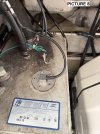
Bring the red/yellow/black wire over to the new sender and trim as needed, leaving an extra foot in case we ever have to cut/reconnect in the future (you shouldn’t need to).
Strip the yellow and black wires (remember we’re not using the red wire here so it can be cut back), slip on some shrink tubing and solder them to the sender wires. Although there is no actual polarity with the sender (it’s really just a fancy variable resistor), solder black-to-black and yellow-to-pink, as it will look cleaner.
(See picture 8)
Review the installation and use cable tie wraps throughout so that the wires don’t interfere with anything and it looks as tidy as possible.
Replace the aft cabin side wall, upper trough cover, gauge panel screws and cockpit switch panel screws.
(See pictures 9 and 10)
The END
Total parts cost: About $200 (including the hole saw and snake) plus a couple adult beverages for my helper
Elapsed time: About 6 hours and well worth my future sanity.
Fuel Sender: KUS 33-240 ohm model KUS-SSL20 (fisheriessupply.com) with cork gasket or optional nitrile gasket, model KUS JSR00181.
Wire: 50 feet of red-yellow-black 16awg jacketed wire (Amazon #B0CX1DBFDP). I really wanted just yellow and black 16AWG conductors but I was unable to find that combo alone.
Fuel Gauge: KUS black face/bezel model KUS-CPFR-BB-240-33 (fisheriessupply.com)
Terminal strip: International Connector model 0113-10-3640-05 (Amazon #B08BDS8L3N)
Wire crimp connectors - Forks and Loops (blue)
Solder and shrink wrap
Fiberglass snake (Amazon item # B07PTSY26L)
Lenox Tools 2-1/8” bi-metal hole saw (Amazon # B004YK5D68)
The prep:
In the aft cabin, remove the square trough cover on the upper left. Once that is out, you can remove the entire starboard side wall panel (not just the small access panel). This exposes the holding tank and rigging tube area
Open the aft generator access panel and remove.
Clean the area around the existing diesel tank sender with a stiff bristle brush. Vacuum up any debris.
In the cabin, remove the breaker panel screws and carefully let it droop forward.
In the helm area, remove the gauge panel screws and the cockpit switch panel screws.
Run the sender wire up to the helm area.
Locate the opening of the aft rigging tube, next to the starboard side of the diesel tank. The rigging tube is up fairly high and is easily accessible and this is where we’ll insert the electrical snake.
(See picture 1)
Insert the snake and work it through to the far end of the rigging tube. It will appear behind the holding tank on the starboard side of the aft cabin.
(See picture 2)
There are two rigging tubes which terminate behind the holding tank. The snake will exit from the larger of the two rigging tubes. Once the snake is visible, attach the red/yellow/black wire to the end of the snake. Tape it good with vinyl electrical tape so it doesn’t easily come apart.
(See pictures 3 and 4)
Pull the wire back through the rigging tube towards the tank area. (This is best done with a helper.) Leave about four feet of wire so we’ll have plenty of slack to connect to the tank sender. Note that with a helper, snaking the rigging tube and pulling the wire back through was fairly easy and took us less than 10 minutes total. Also note that the remaining part of this project went quicker after sending my helper home .
Route the wire over the waste vacuum pump and into the upper-left trough.
(See picture 5)
Fish the wire up from the trough into the electrical panel area (again, fairly easy). I mounted a small marine-rated terminal strip on the back wall of the panel area. It will make the necessary connections a lot cleaner and easier to troubleshoot if needed later.
(See picture 6)
Note that for the wire from that runs from the fuel tank sender to the terminal strip, the Red conductor is not used and can be cut back on both ends and covered with a piece of shrink wrap. For this tank area-to-helm wire run alone, we used a little less than 25 feet of wire.
Make the electrical connections.
Strip the yellow and black wires, add fork terminals to them and connect them to the bottom of terminal strip.
Run a (separate) black ground wire from a good DC ground buss to the black wire already on the bottom of the terminal strip.
Run a separate piece of the red/yellow/black wire, from the top of the terminal strip area up to the cockpit switch panel area, Again, we will not be using the red wire and it can be cut back on both ends. Leave plenty of slack to be able to reach the back of the gauge area.
In the electrical panel area, connect the BLACK wire to the other two black wires already on the terminal block. Connect the YELLOW wire to the yellow wire already on the terminal block.
(See picture 7)
Mount The Gauge.
Pick a spot in the gauge panel for the new gauge with plenty of space behind. I placed a rag under and behind the gauge panel to catch the cuttings.
Replace the gauge panel and screw it tight so it can be drilled in place. Drill a pilot hole at the center of where the new gauge will be mounted. Start with a small bit (I used a 1/8” bit) as it is less likely to move off your “center” mark than a larger bit would. I then enlarged the hole with a 1/4” bit.
Just a tip here: Do not rely on the hole saw’s pilot bit for your first hole as you might ruin the gauge panel if the hole saw “skates” AND IT WILL no matter how steady you think you are!!
Next, using your 2-1/8” bi-metal hole saw, start drilling the front of the panel in REVERSE (COUNTER-CLOCKWISE) rotation. This will lessen the damage to the vinyl trim covering. Once the vinyl trim covering has been cleanly cut, you can start cutting into the metal using the normal (forward/clockwise) hole saw rotation.
To lessen the chance of gouging the vinyl, drill approximately halfway into the metal and then flip the gauge panel forward so you can can finish the drilling from the back side. If you choose to drill through the entire thickness from the front, you risk having the hole saw jump when it finally cuts through. To prevent damage to the helm area while drilling, I used a wooden 4X4 under the panel (covered with blue masking tape) to finish the cut from the back side.
Insert the new fuel gauge and fasten it to the panel using the screw-on retainer. There is a rubber gasket embedded into the gauge so you shouldn’t need any silicone to seal against the weather.
Connect The Gauge Wires.
The gauge wires attach to the gauge with a removeable connector. If already plugged into the gauge, disconnect the connector so we can solder the connections easier.
Strip the yellow and black wires (about 3/8”) coming from the terminal strip up to the switch panel area. As before, cut the red wire back and cover it with a small piece of shrink tubing. Since we have two new wires now coming from the switch panel (the red power wire and the blue lighting wire), tie them together with the black/yellow/red sender wire so we can snake a single wire group to the gauge.
Place a small piece of shrink tubing over the black wire and solder it to the gauge connector’s BLUE wire (DC ground).
Place shrink tubing over the yellow wire and solder it to the gauge connector’s BLACK wire (fuel sender signal).
Solder a (separate) piece of red wire to the gauge’s RED wire (+12V) and slide on a piece of shrink. I attached the other end of this red wire to the ACC switch output on my switch panel (unused spare), leaving enough slack to reach the back of the gauge area.
Note: The Genset Control Panel on the back side of the electrical panel, is a PCB (Printed Circuit Board) unit. It is possible that you could find +12V on that PCB to power the gauge (that was my original intent), instead of using a switch on the helm switch panel like I did. After looking things over, I determined it was a bit too risky.
For the gauge lighting, solder a piece of wire (I used blue to match the Grady color code), to the orange gauge wire for red-color backlighting, and slide a piece of shrink tubing over it.
Connect the other end of the lighting wire to any one of the blue lighting wires that run across all the cockpit panel switches. I connected it to the light feed on the furthest switch to the right by cutting off the factory female solderless crimp connector, stripping the factory blue and new blue wires, and marrying them in a “yellow” size crimp connector.
Once everything is connected, shrink all shrink tubing to seal those new soldered connections. After shrinking everything, I placed all the new wires in some 3/4" split-loom for the short run from the switch panel to the gauge area and to keep things looking neat.
And now for the diesel tank end of things…
Remove the five fuel sender screws and retain. You’ll need them later for the new sender. Carefully remove the old sender, and place on some newspapers or other absorbent material. Vacuum again around the opening of the tank.
Important info BEFORE you insert the new sender into the tank: The threaded holes in the tank are not evenly spaced which means the sender and supplied gasket have to be installed in a certain position. Unless you’re a big fan of the trial-and-error thing, the easiest path here is to place the gasket alone over the holes before you place the new sender into the tank. The gasket has a small 6th hole for orientation purposes. If you’re looking at the tank, this orientation hole should be at your 3 o’clock position. If the holes in the gasket don’t line up with the threaded screw holes, flip the gasket over.
Once everything lines up nicely, insert the fuel sender through the gasket and into the tank, with the sender wires pointing toward the 3 o’clock position. Replace the five screws and tighten.
Wire Up The New Sender
Bring the red/yellow/black wire over to the new sender and trim as needed, leaving an extra foot in case we ever have to cut/reconnect in the future (you shouldn’t need to).
Strip the yellow and black wires (remember we’re not using the red wire here so it can be cut back), slip on some shrink tubing and solder them to the sender wires. Although there is no actual polarity with the sender (it’s really just a fancy variable resistor), solder black-to-black and yellow-to-pink, as it will look cleaner.
(See picture 8)
Review the installation and use cable tie wraps throughout so that the wires don’t interfere with anything and it looks as tidy as possible.
Replace the aft cabin side wall, upper trough cover, gauge panel screws and cockpit switch panel screws.
(See pictures 9 and 10)
The END
Total parts cost: About $200 (including the hole saw and snake) plus a couple adult beverages for my helper
Elapsed time: About 6 hours and well worth my future sanity.
Attachments
-
 Picture 1 (Aft rigging tube entrance).jpg381.6 KB · Views: 14
 -
 Picture 2 (Equipment Area).jpg273.3 KB · Views: 13
 -
 Picture 3 (Rigging Tube exit in equipment area).jpg187.5 KB · Views: 12
 -
 Picture 4 (Rigging tube exit with snake).jpg202.8 KB · Views: 12
 -
 Picture 5 (Cable trough).jpg286.2 KB · Views: 13
 -
 Picture 6 (Wire up into helm area).jpg249.2 KB · Views: 12
 -
 Picture 7 (Terminal Strip).jpg180.7 KB · Views: 12
 -
 Picture 8 (Tank with wired sender).jpg333.3 KB · Views: 13
 -
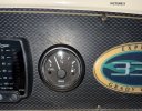 Picture 9 (Gauge on Dashboard).jpg381.5 KB · Views: 14
 -
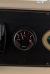 Picture 10 (Gauge with Red Backlight).jpg169.5 KB · Views: 14

