Bildge pump fuse

Bdsp1234

Well-Known Member
Joined
Jan 8, 2019
Messages
155
Reaction score
14
Points
18
Age
66
Model
Seafarer
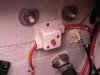
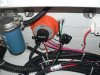
I’ve determined that my forward bilge pump needs replacing. Problem is that I need to increase from a 5 amp fuse to a 7.5 amp fuse. I can’t locate an inline fuse. Does Grady use the breaker/reset as the fuse?


Thanks
 

Toothpick 10

Well-Known Member
Joined
Oct 17, 2017
Messages
169
Reaction score
42
Points
28
Location
Newburyport, MA
Model
Islander
The fuse to my front bilge pump is located in my rear battery compartment. It took me a little while to locate it.
 

wrxhoon

Well-Known Member
Joined
Apr 4, 2012
Messages
957
Reaction score
290
Points
63
Location
Sydney Australia
Yes mine are there as well because they bypass the 1-2 both off switch. They work when the batteries are off so the boat doesn't sink if left on the water.
 

Bdsp1234

Well-Known Member
Joined
Jan 8, 2019
Messages
155
Reaction score
14
Points
18
Age
66
Model
Seafarer
Guys, can you be more specific about location. I do know there is a reset mounted on the transom. And yes it has to be a direct hookup to battery so float switch operates on auto. If you can take a picture toothpick I would really appr crate your help.

This forum is awesome.
 

wrxhoon

Well-Known Member
Joined
Apr 4, 2012
Messages
957
Reaction score
290
Points
63
Location
Sydney Australia
You will find them both, aft and rear, near to 1-2 both off switch. They are in waterproof fuse holders mine are mounted on the transom near the switch. The breaker you are talking about does all the power to the helm.
 

wspitler

GreatGrady Captain
Joined
May 16, 2011
Messages
1,306
Reaction score
289
Points
83
Location
Inglis, FL
Model
Express 330
The "reset" you mentioned is the circuit breaker for the pumps. It is directly off the battery buss. There is no in-line fuse.
 

seasick

Well-Known Member
Joined
Aug 19, 2008
Messages
9,071
Reaction score
1,292
Points
113
Location
NYC
The auto function of the bilge pumps has to be an unswitched feed but that doesn't necessarily mean that you will find a wire and a fuse directly connected to the positive terminal of the battery. On one of my boats, the feed is wired to the back of the battery switch but to the always hot terminal ( the common one that is fed from the battery directly).
On both my boats, the fuse is inline and not a breaker although a breaker would be acceptable per ABYC specs. It is also common that when you have aft and forward pumps and at least two batteries that each pump is fed off a different battery.
 

Toothpick 10

Well-Known Member
Joined
Oct 17, 2017
Messages
169
Reaction score
42
Points
28
Location
Newburyport, MA
Model
Islander
You will find them both, aft and rear, near to 1-2 both off switch. They are in waterproof fuse holders mine are mounted on the transom near the switch. The breaker you are talking about does all the power to the helm.

The boat is currently shrink wrapped for the winter, so it's difficult for me to get in for a photo, but this description by wrxhoon is spot on. There are waterproof fuse holders screwed in next to the battery switch.
 

wrxhoon

Well-Known Member
Joined
Apr 4, 2012
Messages
957
Reaction score
290
Points
63
Location
Sydney Australia
For those of you interested have a look how they are in my 228G 2013 model but it was exactly the same in my old 228 as well. Several other Grady's I have seen have the same set up.
They are wired direct from the off, 1, 2 all , switch , obviously picked up before the switch so they are always powered for obvious reason.
The 40w circuit breaker with the red reset button supplies power to the helm.
 

Attachments

  • Grady power switch 001.JPG
    Grady power switch 001.JPG
    1.7 MB · Views: 37
  • Grady power switch 002.JPG
    Grady power switch 002.JPG
    1.7 MB · Views: 36
  • Grady power switch 003.JPG
    Grady power switch 003.JPG
    1.6 MB · Views: 36
  • Grady power switch 004.JPG
    Grady power switch 004.JPG
    1.6 MB · Views: 31
  • Grady power switch 005.JPG
    Grady power switch 005.JPG
    1.9 MB · Views: 35
  • Like
Reactions: ilmmct and Bdsp1234

Bdsp1234

Well-Known Member
Joined
Jan 8, 2019
Messages
155
Reaction score
14
Points
18
Age
66
Model
Seafarer
For those of you interested have a look how they are in my 228G 2013 model but it was exactly the same in my old 228 as well. Several other Grady's I have seen have the same set up.
They are wired direct from the off, 1, 2 all , switch , obviously picked up before the switch so they are always powered for obvious reason.
The 40w circuit breaker with the red reset button supplies power to the helm.
Wow, first off that isn’t one clean battery area. And thank you. I would have had a hard time locating. Awesome.
 

wrxhoon

Well-Known Member
Joined
Apr 4, 2012
Messages
957
Reaction score
290
Points
63
Location
Sydney Australia
Thanks, my boat is 2013 model besides I like to keep them clean. This is not the battery area , it's the fuel area as you can see by the fuel filter. On the 4 stroke boats you have both batteries on the port side and fuel on the starboard. On my old 228 I had oil tank and one battery on the port side and another battery on the starboard.
As you can see mine have 5 amp fuses as well , of course I can change them if I install bigger pumps. You will notice one is marked aft float and the other one FWD float.
I hope that helps you and maybe others....
 

wrxhoon

Well-Known Member
Joined
Apr 4, 2012
Messages
957
Reaction score
290
Points
63
Location
Sydney Australia
For guys that have older boats, the 40 amp circuit breaker on our boats is not a quality marine breaker . In my old boat you could see some rust marks under the breaker so I pulled it off soon after I got the boat and it had corrosion so I replaced it with a quality bussman marine breaker .
 

seasick

Well-Known Member
Joined
Aug 19, 2008
Messages
9,071
Reaction score
1,292
Points
113
Location
NYC
Thea breaker is also switched by the battery switch and could not be the feed for the bilge pumps (auto mode feed)
 

Bdsp1234

Well-Known Member
Joined
Jan 8, 2019
Messages
155
Reaction score
14
Points
18
Age
66
Model
Seafarer
Thanks guys. I’ve located the fuse ( brown and red wire) for the forward bildge. Going to replace tomorrow or Sunday. I guessing that the circuit breaker will also need replacing because it’s rated 5 amp
 

wrxhoon

Well-Known Member
Joined
Apr 4, 2012
Messages
957
Reaction score
290
Points
63
Location
Sydney Australia
. I guessing that the circuit breaker will also need replacing because it’s rated 5 amp
The circuit breakers for the bilge pumps are on the panel where the manual switches are. Just replace the fuse with a 5 amp and you should be fine. If you replaced the bilge pump with one that requires 7.5 amp fuse then you need a 7.5 but you have to make sure the wire that go to the pump are thick enough to carry the current and it is a long run to the front pump, if it gets very hot you could have serious problem.
My boat has 1200 gal bilge pumps one would draw about 3.5 amp so the 5 amp fuse is adequate.
 

seasick

Well-Known Member
Joined
Aug 19, 2008
Messages
9,071
Reaction score
1,292
Points
113
Location
NYC
The feeds for the auto function and the manual activation are totally separate with respect to the +12volts. They will share a common ground for each pump. In addition as mentioned, the auto feed is hard wired to the battery feed usually protected by an inline fuse. The manual feed will usually route through a switch and breaker on the DC panel and that panel has a master breaker as well as being fed from the accessory 12v buss that ends up at the battery switch near the batteries. It also may have a breaker near the battery switch or near the battery depending on how far or close the switch is to the battery.
For trouble shooting;
If either one of manual, or automatic work, the pump is good as is the common ground.
If neither work you could have a bad pump, bad common ground and possible bad feeds on bot the manual and automatic wiring. This is much less likely than a bad pump or ground issue (or bad connections).
Bad connections are the more common fault.
 
  • Like
Reactions: ilmmct

Fishtales

Well-Known Member
Joined
Jan 31, 2005
Messages
7,490
Reaction score
1,161
Points
113
Make sure you secure all electrical connections well. Soldering is best but you can use water rated butt connectors. I use the liquid plastic insulator and then tape (friction followed by plastic electrical) for the best waterproof connection.
 

seasick

Well-Known Member
Joined
Aug 19, 2008
Messages
9,071
Reaction score
1,292
Points
113
Location
NYC
Make sure you secure all electrical connections well. Soldering is best but you can use water rated butt connectors. I use the liquid plastic insulator and then tape (friction followed by plastic electrical) for the best waterproof connection.
Funny you should say that. ABYC regs do not allow soldered connections since they are brittle and can separate under vibration
Here is the regs:

Another common misconception dictates that the best of all connections is a soldered connection. However with stranded wire, the solder bonds the individual strands together, making a solid, inflexible wire. ABYC standards prohibit soldering as the sole means of making a connection because the newly solid wire is subject to cracking or breaking through vibration and flexing. A more practical solution is to use a crimp connector described above. Wires should never be joined simply by soldering and taping (or heat shrink); however, if solder is used, use only 60%/40% rosin core or solid solder, soldering after the butt connector is crimped. Acid core solder as used in plumbing may never be used in any electrical wiring.