Guest Battery Switch Question

Blaugrana

Well-Known Member
Joined
Sep 16, 2019
Messages
703
Reaction score
107
Points
43
Age
40
Location
Bayville, New Jersey
Model
Seafarer
Good Evening

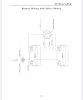
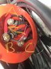
I am trying to understand how this switch is wired. Please let me know if the below is correct.

A - Battery #1
B - Battery #2, Front Float Switch, Stern Float Switch, Memory Switch, Unknown Cable (Marked with Arrow)
C - Starter Cable, Cable to Helm Circuit Breaker

Questions:
1. What is the Unknown Cable with the arrow? Tried tracing it with no luck and not sure if anyone has any hints

2. What is a “memory wire” and it’s purpose?

3. For the starter and helm cables, is it better to have the starter underneath or on top? I moved it underneath after taking this pic so it would have the greatest contact with the switch

4. How does my engine actually charge the batteries? Is that the mystery cable?

Thanks - I tried googling with no luck in finding the wiring diagram for it.
 

Attachments

  • 835F6FAB-41EA-485D-8919-67B5667FBB44.jpeg
    835F6FAB-41EA-485D-8919-67B5667FBB44.jpeg
    486.9 KB · Views: 3

seasick

Well-Known Member
Joined
Aug 19, 2008
Messages
9,141
Reaction score
1,310
Points
113
Location
NYC
Memory wire is a feed for your stereo to keep your preset stations.

I prefer the two auto bilge pumps to be connected to different batteries so that if a battery dies at least one pump is operational.
If by starter on top you mean which lug is preferred in what order, it doesn't make much difference as long as the surfaces of the lugs sit flat. Sometimes that means that if one lug is larger than the other, it usually goes on first followed by the next smaller size.
Not sure what the mystery cable is but it might be the feed for the accessories.That feed would be switched so if the stud it is connected to is the output of the switch ( bat 1 or 2 or both) that is what it probably is for.
 

Blaugrana

Well-Known Member
Joined
Sep 16, 2019
Messages
703
Reaction score
107
Points
43
Age
40
Location
Bayville, New Jersey
Model
Seafarer
Memory wire is a feed for your stereo to keep your preset stations.

I prefer the two auto bilge pumps to be connected to different batteries so that if a battery dies at least one pump is operational.
If by starter on top you mean which lug is preferred in what order, it doesn't make much difference as long as the surfaces of the lugs sit flat. Sometimes that means that if one lug is larger than the other, it usually goes on first followed by the next smaller size.
Not sure what the mystery cable is but it might be the feed for the accessories.That feed would be switched so if the stud it is connected to is the output of the switch ( bat 1 or 2 or both) that is what it probably is for.

Thanks....

So I looked again while I was out this morning. I believe that mystery cable is separate from my cable going to the Engine from C. However, it loops about 2-3 ft and the cables merge together (just the rubber outside), but can’t see if stays the whole way to the engine or not.
 

wspitler

GreatGrady Captain
Joined
May 16, 2011
Messages
1,319
Reaction score
294
Points
83
Location
Inglis, FL
Model
Express 330
I'd say your mystery cable, with the arrow, is an alternate (aux) charge lead from your engine. Yamahas are designed with two charging outputs, but only one is normally connected at installation. Note the red covering. I'd say the aux lead is wired direct to the #2 battery so that you would normally select battery #1 for starting, running and charging while underway. Battery #2 (not selected) will then be charged by the aux charge lead anytime the engine is running. This is all easily confirmed with a volt meter while the engine is running.
 
  • Like
Reactions: SkunkBoat

Blaugrana

Well-Known Member
Joined
Sep 16, 2019
Messages
703
Reaction score
107
Points
43
Age
40
Location
Bayville, New Jersey
Model
Seafarer
I'd say your mystery cable, with the arrow, is an alternate (aux) charge lead from your engine. Yamahas are designed with two charging outputs, but only one is normally connected at installation. Note the red covering. I'd say the aux lead is wired direct to the #2 battery so that you would normally select battery #1 for starting, running and charging while underway. Battery #2 (not selected) will then be charged by the aux charge lead anytime the engine is running. This is all easily confirmed with a volt meter while the engine is running.

Thanks I thought the same but from what I read the OX66 doesn’t have two charging leads, but then again I only see 1 cable at the switch coming from the engine outside of the one running to the starter.

I have never tested the 2nd battery while running on the 1st. Next time I will to see if that is what it’s doing
 
  • Like
Reactions: glacierbaze

ilmmct

Well-Known Member
Joined
Jul 2, 2019
Messages
74
Reaction score
12
Points
8
Age
63
Location
Wilmington, NC
Model
Explorer
GW provides a copy of the user manual online ... not sure this will provide you the info you need, you but here is the link and and “wiring” excerpt for your model:


Attachments

  • 98B7E40D-89D1-496A-B8CA-E3D79E86B1EE.jpeg
    98B7E40D-89D1-496A-B8CA-E3D79E86B1EE.jpeg
    139.4 KB · Views: 1

glacierbaze

Well-Known Member
Joined
Jul 6, 2012
Messages
2,344
Reaction score
599
Points
113
Age
75
Location
Chapel Hill and Pine Knoll Shores, NC
Model
Seafarer
53C30A43-627E-4208-9BE6-2AAFB6FA8C11.jpeg
This flat starter cable has three wires. Looks like it goes to the helm, but it is just tucked out of the way there and doubles back on itself just out of sight. One large lead connects to the negative on battery one. The other large lead is the square looking cable with the red sleeve, on terminal C. There is a third, smaller wire which is the black cable with red sleeve on terminal B. The other end of the cable, all three leads, go to the engine bundle.
E4EB817C-7AA4-4D3B-BE62-2ED2D0C892FE.jpeg
My switch.
Terminal A is battery number one, pink memory, and brown and white bilge.
Terminal B is battery number two, brown and red bilge, and the small lead from the starter cable above.
Terminal C is the starter cable above, and the red and black cable runs through the
40 amp breaker, and to the helm main.
 
Last edited:

Blaugrana

Well-Known Member
Joined
Sep 16, 2019
Messages
703
Reaction score
107
Points
43
Age
40
Location
Bayville, New Jersey
Model
Seafarer
Thanks for sharing this!!!

Per the advice, I will adjust my floats so they are not on the same battery, which is
View attachment 16030
This flat starter cable has three wires. Looks like it goes to the helm, but it is just tucked out of the way there and doubles back on itself just out of sight. One large lead connects to the negative on battery one. The other large lead is the square looking cable with the red sleeve, on terminal C. There is a third, smaller wire which is the black cable with red sleeve on terminal B. The other end of the cable, all three leads, go to the engine bundle.
View attachment 16031
My switch.
Terminal A is battery number one, pink memory, and brown and white bilge.
Terminal B is battery number two, brown and red bilge, and the small lead from the starter cable above.
Terminal C is the starter cable above, and the red and black cable runs through the
40 amp breaker, and to the helm main.


Thanks for sharing this!!!

Per the advice, I will adjust my floats so they are not on the same battery, which is what you have here.

As for the previous diagram, it looks like this wire is the 12v constant. I am still learning so have no clue what is it’s purpose and where it runs on the engine. I’ll have to see where it runs when I get back to my boat.
 

SkunkBoat

Well-Known Member
Joined
Oct 12, 2017
Messages
4,227
Reaction score
1,465
Points
113
Location
Manasquan Inlet NJ
Website
www.youtube.com
Model
Express 265
My ox66s had aux charging wires and they worked.
Looks like you have an Aux charging wire. If its connected inside your motor and is working then you don't need an ACR. When your switch is in position 1 the starter battery(Batt1) will charge thru the motor start wire(C in your diagram) and the house battery (Batt2) will charge thru the aux wire that is on the B terminal in your diagram.
If your Aux is charging then you could move the House feed from C to B (or directly to the House Batt2). Then your House would always run on Batt2, always charge, and it would be isolated from the starter.

Simple test is to disconnect the "aux" wire at the switxh and measrue the voltage with motor off (0V) and motor running (about 13.4V)...or take the cover off the motor and follow the wire to the plug end near the voltage regulator.
 

Blaugrana

Well-Known Member
Joined
Sep 16, 2019
Messages
703
Reaction score
107
Points
43
Age
40
Location
Bayville, New Jersey
Model
Seafarer
My ox66s had aux charging wires and they worked.
Looks like you have an Aux charging wire. If its connected inside your motor and is working then you don't need an ACR. When your switch is in position 1 the starter battery(Batt1) will charge thru the motor start wire(C in your diagram) and the house battery (Batt2) will charge thru the aux wire that is on the B terminal in your diagram.
If your Aux is charging then you could move the House feed from C to B (or directly to the House Batt2). Then your House would always run on Batt2, always charge, and it would be isolated from the starter.

Simple test is to disconnect the "aux" wire at the switxh and measrue the voltage with motor off (0V) and motor running (about 13.4V)...or take the cover off the motor and follow the wire to the plug end near the voltage regulator.

This made my night and hopefully saved me some money as I was about to purchase the kit from blue sea system.

Your feedback is interesting and thinking it would solve my voltage problem. It still exists but thecranking battery hides it. I tried chasing today but couldn’t measure it like before as too many amps were flowing and everything seemed good. Going to ask the mechanic to switch the starter to another one as they didn’t charge me the first time for a new one and all the labor, but I think it’s my issue.

By moving the house feed to the house battery, it would separate the voltage going to start my engine from my house feed where all the electronics are. This would keep them on separate circuits and eliminate any voltage drops from impacting my electronics. Is that correct?

Also, regarding the simple test. I am not following. If I disconnect the aux cable, are you saying to measure that terminal (positive of multimeter) to any ground? With engine off should be 0v and running around 13.4v? After typing that I think I got it, kept thinking you meant to measure the house battery.
 

wspitler

GreatGrady Captain
Joined
May 16, 2011
Messages
1,319
Reaction score
294
Points
83
Location
Inglis, FL
Model
Express 330
You don't need to disconnect anything. Select Batt #1 and check voltage at each positive terminal while running on each battery. The aux lead should produce 13+ volts on Batt #2 and the normal charging circuit should produce 13+ volts on #1 battery.
 

SkunkBoat

Well-Known Member
Joined
Oct 12, 2017
Messages
4,227
Reaction score
1,465
Points
113
Location
Manasquan Inlet NJ
Website
www.youtube.com
Model
Express 265
This made my night and hopefully saved me some money as I was about to purchase the kit from blue sea system.

Your feedback is interesting and thinking it would solve my voltage problem. It still exists but thecranking battery hides it. I tried chasing today but couldn’t measure it like before as too many amps were flowing and everything seemed good. Going to ask the mechanic to switch the starter to another one as they didn’t charge me the first time for a new one and all the labor, but I think it’s my issue.

By moving the house feed to the house battery, it would separate the voltage going to start my engine from my house feed where all the electronics are. This would keep them on separate circuits and eliminate any voltage drops from impacting my electronics. Is that correct?

Also, regarding the simple test. I am not following. If I disconnect the aux cable, are you saying to measure that terminal (positive of multimeter) to any ground? With engine off should be 0v and running around 13.4v? After typing that I think I got it, kept thinking you meant to measure the house battery.

Disconnect your mystery wire and measure the unconnected wire. positive lead on wire, negative lead on battery negative. That will tell you for sure that you are not reading the battery and that the voltage is from the motor. Be sure to take caution when the motor is running as the disconnected wire is live. Don't let it touch things!
 

SkunkBoat

Well-Known Member
Joined
Oct 12, 2017
Messages
4,227
Reaction score
1,465
Points
113
Location
Manasquan Inlet NJ
Website
www.youtube.com
Model
Express 265
These might help you follow whats going on. First two are how it is now (assuming that IS an AUx cable). Last one moves the House panel to Batt2.


Batt Switch_1.jpeg
Switch Position 1 ( The Normal operating position) Batt1 starts Motor, motor charges Batt1, House panel fed from Batt1(and motor Start wire)
If the Aux wire is working, Batt2 is charging from the Aux cable

Batt Switch_2.jpeg
Switch Position 2. Batt2 starts Motor, motor charges Batt2, House panel fed from Batt2 (and motor Start wire)
If the Aux wire is working, Batt2 is charging from the Aux cable. In this case the Start Cable AND Aux Cable are connected to Batt2 and the House panel.

Batt Switch_3.jpeg
Here I have moved the House from "Feed" to the Batt2 Pos terminal.
Switch Position 1 ( The Normal operating position) Batt1 starts Motor, motor charges Batt1
If the Aux wire is working, Batt2 is charging from the Aux cable.

So you are always charging both batteries (when motor is running) and the batteries are isolated from each other. When you shut off your motor, your House runs on the Batt2 and you don't have to throw the switch. Your motor starts on Batt1 and it is not being used to run anything but a bilge pump.

If you have an emergency you can still start the motor from either battery or Both using the switch
 
  • Like
Reactions: ilmmct

Blaugrana

Well-Known Member
Joined
Sep 16, 2019
Messages
703
Reaction score
107
Points
43
Age
40
Location
Bayville, New Jersey
Model
Seafarer
Awesome, thanks for the diagrams. I started doing it last night before kids bedtime festivities kicked off...

My plan is to confirm that the cable is truly charging this weekend before making any changes.

The one thing on my mind is whether the house feed being with battery 2on the switch means that my electronics always have power even when the switch is off. Is that correct ?
 

wspitler

GreatGrady Captain
Joined
May 16, 2011
Messages
1,319
Reaction score
294
Points
83
Location
Inglis, FL
Model
Express 330
His third drawing would work that way, but should not be done. You always want the ability to turn off all power to the house without having to manually disconnect a battery. On my other boat I have the same setup as the second drawing and use a deep cycle battery as Batt #2 since it will be discharged when the motor is not running. I switch the house to Batt #2 when over-nighting, or drifting/anchored for any prolonged period.
 

Blaugrana

Well-Known Member
Joined
Sep 16, 2019
Messages
703
Reaction score
107
Points
43
Age
40
Location
Bayville, New Jersey
Model
Seafarer
Ok, but I think the approach would solve my problem once I replace my switch.

Assuming that cable is an Aux charger, I can get the blue sea dual circuit plus battery switch only and it will allow me to have two isolated circuits running at the same time.

Thanks for the feedback and all the effort.
 

SkunkBoat

Well-Known Member
Joined
Oct 12, 2017
Messages
4,227
Reaction score
1,465
Points
113
Location
Manasquan Inlet NJ
Website
www.youtube.com
Model
Express 265
Awesome, thanks for the diagrams. I started doing it last night before kids bedtime festivities kicked off...

My plan is to confirm that the cable is truly charging this weekend before making any changes.

The one thing on my mind is whether the house feed being with battery 2on the switch means that my electronics always have power even when the switch is off. Is that correct ?
I did forget to mention, You should replace the House red button breaker with a switchable breaker ( or put a mini On/Off battery switch). I THINK you already replaced the breaker, right?