Question on auto bilge pump wiring 209 Escape

nightfighter

Well-Known Member
Joined
Dec 1, 2007
Messages
71
Reaction score
0
Points
6
Location
Marblehead
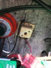
1993 Escape. A lot of winter projects so a lot of parts and wiring were affected. Almost all back together. BUT.... no auto bilge function. Found a separated inline fuse. But it goes to a 40 amp circuit breaker.... This is a poor pic of the very dirty interior transom where the battery switch sits, next to the batteries. Any thoughts? Wondering if this was how GW wired it back in 1993? What does yours look like?
 

Attachments

  • IMG_8136.JPG
    IMG_8136.JPG
    747.2 KB · Views: 8

DennisG01

GreatGrady Captain
Joined
Sep 1, 2013
Messages
6,863
Reaction score
1,218
Points
113
Location
Allentown, PA & Friendship, ME
Model
Offshore
That 40a breaker is not for the bilge pump float switch. The 40a could likely be for the dash power feed. However, the float switch could be wired to the hot side of that breaker as from your description it sounds like the float switch power wire leads to there? Kind of strange, but oh well. The downside to that is that the float would only be active with the battery switch to an "on" position. Not what you want.

That said, all you really need to do is run the float power feed wire to a constant hot such as a battery or the the line side of one of the battery switch posts.
 

nightfighter

Well-Known Member
Joined
Dec 1, 2007
Messages
71
Reaction score
0
Points
6
Location
Marblehead
Dennis, we are thinking along the same lines as I don't see the reason for wiring the hot through the circuit breaker.... That said, I am not sure I have ever observed the bilge pump operating on its own at the dock or mooring. I most often saw the pump come on via the float switch when first underway and the bilge water would shift aft. The goal of course is to have it operate in Auto mode with the switch off. I will connect those two with an inline fuse and test it with a hose at the dock some overcast day. Then of course I will need to test the Sure Bail floating switch as well as all the connections that could have been under water. (I did not get out to it for two weeks that we had a LOT of rain.) This is what told me the auto switch was not working.... Manual switch at dash works fine.
 

Hookup1

GreatGrady Captain
Joined
Oct 16, 2007
Messages
2,679
Reaction score
730
Points
113
Age
69
Location
Cape May, NJ
Model
Islander
This is factory wiring for my boat. The bilge pump fuse in attached to the bottom edge of that switch board. It's a waterproof holder that snaps together. This is wired to the battery side of the switch so it's always on. The other wire goes into the harness. At the bilge pump you have 3 wires. This hot 12-volt +, a switched 12-volt + from the helm manual bilge switch and a ground. There are two fuses - forward and aft bilges.

Bilge fuse.jpeg
 

seasick

Well-Known Member
Joined
Aug 19, 2008
Messages
9,169
Reaction score
1,318
Points
113
Location
NYC
In many cases when there is a separate float switch , there are only two wires from the pump. The two feeds from the float switch and the helm manual switch are wired together to the pump lead. The other pump lead connects to ground
 

SkunkBoat

Well-Known Member
Joined
Oct 12, 2017
Messages
4,292
Reaction score
1,486
Points
113
Location
Manasquan Inlet NJ
Website
www.youtube.com
Model
Express 265
Usually there was an inline ATO blade type fuseholder from the FEED post of the Battery switch. That fed the Float switch. As Seasick said, that connected to the pump with the wire coming from the manual switch.

Get rid of that POS red button breaker. Use an MRCB or 285 type switchable breaker.